1. Preparation before installation
Check device integrity
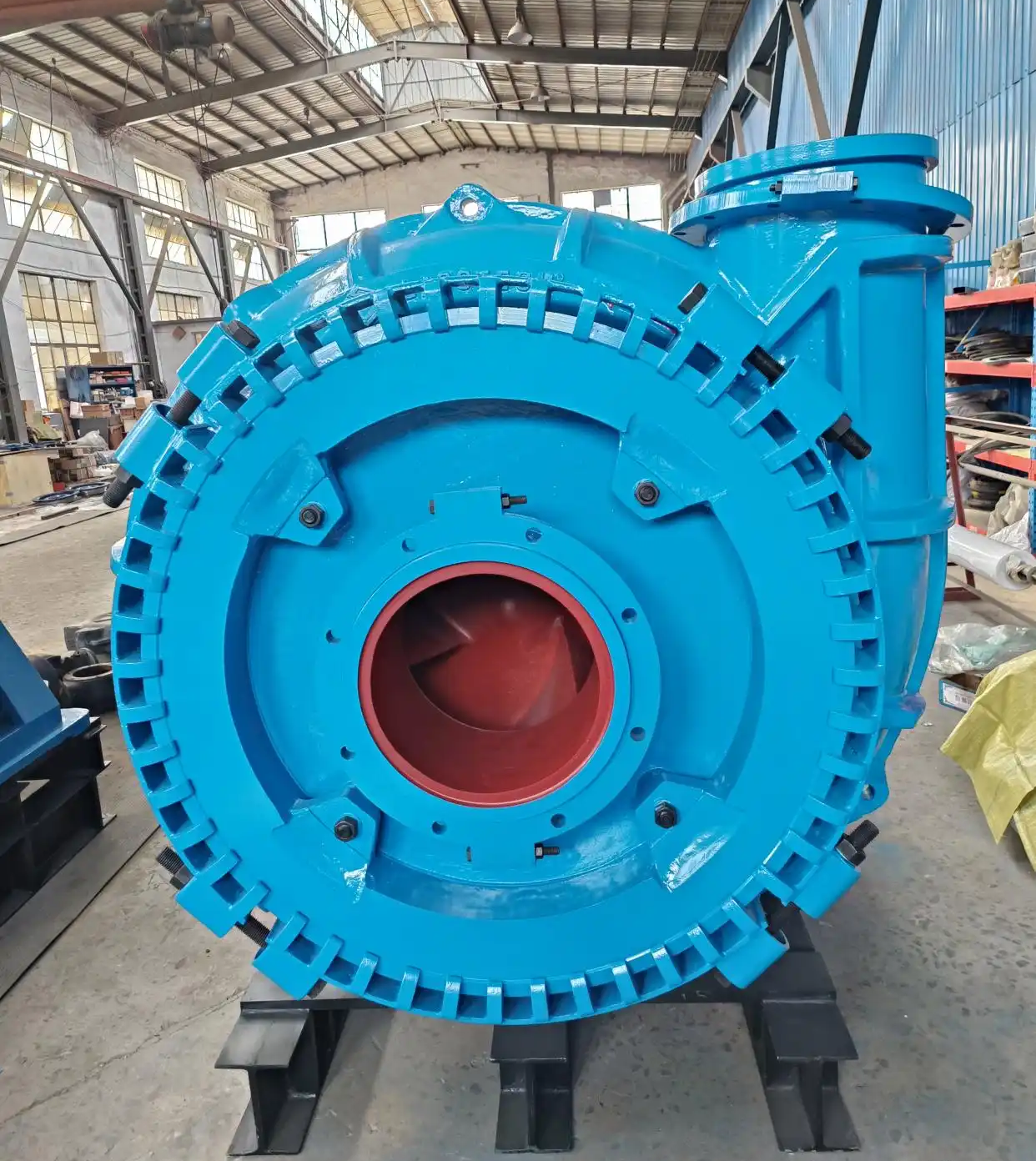
- Before installing the G-type gravel pump, you need to carefully check whether all the components of the pump are complete, including the pump body, impeller, seals, bearings, couplings, etc. Check whether the parts are damaged, deformed or have manufacturing defects. If there are any problems, contact the supplier in time for replacement.
- At the same time, check whether the model and specifications of the pump are consistent with the design requirements to ensure that the selected pump can meet the flow rate, head, medium characteristics and other requirements in actual work.
Installation Basic Preparation
- Prepare a suitable installation foundation according to the size and weight of the pump. For small G-type gravel pumps, they can be installed on a solid concrete foundation or steel base; for large pumps, a specially designed concrete foundation is required, and the size and strength of the foundation must be able to withstand the weight, vibration and torque of the pump during operation.
- The installation foundation must be level, and the level error should generally not exceed ±0.1mm/m. A level meter can be used for measurement and adjustment to ensure that the pump can run smoothly after installation and avoid component wear and operation failures caused by uneven foundation.
Pipeline Connection Preparation
- Prepare pipes that match the pump inlet and outlet. The material, diameter and wall thickness of the pipes should be selected according to the characteristics, flow and pressure requirements of the conveying medium. For pipes conveying gravel, generally choose materials with good wear resistance, such as steel pipes or rubber-lined steel pipes.
- Before connecting the pipeline, clean the debris, rust and dirt inside the pipeline to ensure that the inside of the pipeline is clean and smooth to reduce pipeline resistance and prevent foreign matter from entering the pump body. At the same time, prepare the sealing materials required for pipeline connection, such as rubber sealing rings or sealants, to ensure the sealing of the pipeline connection.
2. Installation Steps
Pump Installation
- Place the G-type gravel pump on the pre-prepared installation foundation and fix the pump body with anchor bolts. When tightening the anchor bolts, tighten them step by step in the order of diagonal lines to ensure the flatness of the pump body installation. At the same time, pay attention to the use of shims, the number and position of shims should be reasonable, and they are used to adjust the levelness of the pump body.
- For vertical G-type gravel pumps, ensure that the pump body is vertical, and the verticality error generally does not exceed ±0.1mm/m. You can use a plumb line or professional verticality measuring tools to check and adjust.
Pipeline Connection
- Inlet pipe connection: Connect the inlet pipe to the pump inlet flange. Pay attention to the direction of the pipe when connecting to ensure that the medium can enter the pump body smoothly. When installing the flange connection, use appropriate bolts and nuts and tighten them according to the specified torque to ensure the tightness of the connection. At the same time, install sealing gaskets between the flanges to prevent medium leakage.
- Outlet pipe connection: Similarly, connect the outlet pipe to the outlet flange of the pump. When connecting the outlet pipe, consider the support and fixation of the pipe to avoid the weight of the pipe being borne entirely by the pump body to avoid damage to the pump body. The connection of the outlet pipe must also ensure good sealing to prevent leakage during operation.
Motor Installation and Coupling Connection
- Install the motor in a suitable position, generally ensuring that the motor shaft and pump shaft are in the same straight line. The motor installation foundation should be firm, and the ventilation and heat dissipation conditions of the motor should be considered.
- For pumps and motors connected by couplings, the coaxiality of the motor shaft and the pump shaft must be accurately adjusted when connecting the coupling. The coaxiality error should generally not exceed ±0.05mm. Tools such as dial indicators can be used for measurement and adjustment. When connecting the coupling, follow the installation instructions of the coupling to ensure that the connection is firm and install the protective cover to prevent personal injury.
Installation of Auxiliary Equipment
- If the pump needs to be equipped with auxiliary equipment such as seal flushing device, cooling device or lubrication device, it should be installed according to the installation instructions of the equipment. For example, for pumps with mechanical seals, the seal flushing pipeline should be installed to ensure that the flushing liquid can effectively flush the seal surface, remove heat and impurities, and extend the service life of the seal.
3. Debugging Steps
Check the Lubrication and Cooling System
- Before commissioning, first check the lubrication system of the pump. For oil-lubricated pumps, check whether the oil level is within the specified range and whether the oil quality is good. If the oil level is insufficient, add an appropriate amount of lubricating oil; if the oil quality deteriorates, replace it in time. For grease-lubricated pumps, check whether the grease filling amount is appropriate.
- At the same time, check whether the cooling system is working properly. If the pump is equipped with a cooling water pipeline, check whether the water pipeline is unobstructed and whether the flow and pressure of the cooling water meet the requirements. Ensuring the normal operation of the lubrication and cooling systems is the key to preventing overheating and component damage during the operation of the pump.
Turn the Gear to Check
- Before the motor is powered on, a cranking check must be performed. Manually turn the coupling to rotate the pump shaft 3-5 times, and check whether the pump shaft can rotate flexibly and whether there is any jamming. If you feel a large resistance or an abnormal sound during the cranking process, stop cranking immediately and check whether there is any foreign matter inside the pump body, whether the impeller is in contact with the pump body, or whether the bearing is damaged.
Jog the Motor to Check the Direction
- After ensuring that the cranking is normal, start the motor. Turn on the motor power briefly and observe whether the direction of the motor and pump is correct. The direction of the G-type gravel pump is generally clearly marked on the pump body. If the direction is wrong, the pump will not be able to suck the medium normally, and may even damage the impeller and pump body. If the direction is wrong, cut off the power immediately and adjust the motor wiring to make the motor turn correctly.
No-load Operation Debugging
- After the motor turns in the correct direction, perform no-load operation debugging. Start the motor and let the pump run for 1-2 hours without load (i.e. the inlet valve is closed and the outlet valve is open). During the no-load operation, closely observe the operation of the pump, including the vibration, noise, temperature, current and other parameters of the pump. Under normal circumstances, the vibration of the pump should be small, the noise should be within the specified range, the temperature should gradually rise but not too high, and the current should be stable below the rated value. If any abnormal situation is found, stop the machine in time to check and eliminate the fault.
Load Operation Debugging
- After the no-load operation is normal, carry out the load operation debugging. Gradually open the inlet valve to allow the medium to slowly enter the pump body, and observe the operating status of the pump. When the medium fills the pump body, adjust the opening of the outlet valve according to actual needs to make the pump run at the rated flow and head. During the load operation process, it is also necessary to pay close attention to the vibration, noise, temperature, current and other parameters of the pump, and check whether there is leakage in the connection of the inlet and outlet pipes. If everything is normal, the load operation debugging time is generally not less than 4-8 hours to ensure that the pump can run stably under load.
Through the above installation and debugging steps, it can be ensured that the G-type gravel pump can be correctly installed and operate normally, providing reliable equipment guarantee for the transportation of media such as gravel.
The content presented in this article is for informational purposes only and may not address all practical scenarios or individual application needs. While we strive to ensure accuracy and clarity, we recommend consulting with a qualified technician or referring to specific technical documentation when dealing with complex systems or customized configurations. If you have any uncertainties, questions about implementation, or wish to explore tailored solutions for your project, please do not hesitate to leave a message below or get in touch with our sales team. We are always ready to provide professional advice and support to help you find the most suitable pumping system for your specific requirements.
The content presented in this article is for informational purposes only and may not address all practical scenarios or individual application needs. While we strive to ensure accuracy and clarity, we recommend consulting with a qualified technician or referring to specific technical documentation when dealing with complex systems or customized configurations. If you have any uncertainties, questions about implementation, or wish to explore tailored solutions for your project, please do not hesitate to leave a message below or get in touch with our sales team. We are always ready to provide professional advice and support to help you find the most suitable pumping system for your specific requirements.